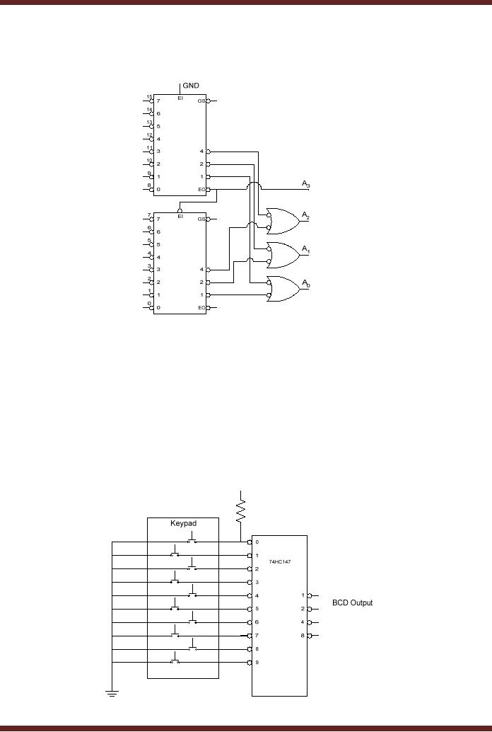

It is very easy and can be easily determined just by looking at the truth table. The first in designing the Combinational Logic device is to find the Boolean Expression for the truth table. Although Encoders like 8:3 is available as neat single package IC like SN74LS148 it is important to know how they are built so that we can make custom encoders for our projects based on the required truth table.
#PROJECT REPORT ON DECIMAL TO BCD PRIORITY ENCODER K MAP HOW TO#
Let us learn how to build one using simple logic gates. Now that we know how an Encoder works and where it is used. In some applications we might have a situation where more than one input could be high (1) in those case we will something called Priority Encoder which we will discuss further in this article.īuilding Encoders using Combinational Logic Designs It is also used in transmitting data efficiently by using lesser wires. These types of Encoder are very useful when we have to reduce the number of pins used on a MCU/MPU or reduce the number of signal carrying wires in PLC and other systems where an array of switch or LED. Okay, what is fancy about converting 4 lines to 2 lines why do we even need it?įor the purpose of understanding we have explained a 4:2 Encoder, but there are other encoder which can taken a higher number of inputs and convert them to lower number of outputs like the 8:3 Encoder, 16:4 Encoder etc. By using this Output bits status the user will be able to trace back to what input signal would have been given to the Encoder. Similarly for each case the output pins will also change its status. For instance when only O1 is high (1) and all the other inputs are low (0) then both the output pins will low (0).

It is also important to know that an ordinary Encoder like the one shown here has a rule that at given time only one input pin should be high so in the following truth table only one input will be high.Įvery possible condition of the input the output is shown in the above truth table. So how do the Encoder convert four signals into two, it can be understood by taking a look at the truth table below.

The four Input Pins are labelled from I0 to I3 and the two output pins are labelled from O0 to O1 If an Encoder has “ n” number of output lines then the number of input lines will be 2 n, in our case the number of output lines is two (n=2) hence the number of input lines should be be (2 2 = 4) four which is exactly the case. It has four inputs and two outputs so the name of this Encoder will be 4:2 Encoder. First let’s determine what the name of this Encoder would be.


 0 kommentar(er)
